Giving Face Book a Try
It would appear that not much has been happening with the project, BUT, nothing could be further from the truth, It's moving at a good clip and too much has happened to write up a single blog post about.
The real issue is that, as much as I really like the blog tools and formatting capabilities I'm horrible about logging in to make updates.
So, I'm going to be giving it a go with a Facebook page because it tend to spend more time there and I'm hoping I'll be a little better about making updates.
If you'd like to keep following my progress, or maybe better put, actually see me post about my progress, please feel free to like and follow my new page at https://www.facebook.com/mycessnasim
If it works out better I probably won't be adding much content here. If it doesn't, or the lack of format control frustrates me I'll be back...
I hope you decide to like and follow my page.
THANKS!!!
Happy Holidays!!!
My Cessna Sim Project

To visit my project web site click on the image above or go to: www.mycessnasim.info
Tuesday, December 23, 2014
Thursday, August 1, 2013
Avionics and Electronics and Programming, Oh My!
This may be a longer than normal post. I have been very lazy about posting updates. SORRY!!!
Much has happened since the last update. And, I typed the update below, more and more kept coming to mind that I had done since the last blog post.
Since the last update we have seen 3 seasons... The transition into winter started slow so I was able to get some more wiring done on the fuselage and I finally got the elevator position sensor done, but then the cold made it impractical to do much more in the garage. I managed a couple days hear and there but not much more. Heading back into Spring with plenty of winter weather early on but I was able to get a little more done as the temps slowly came up.
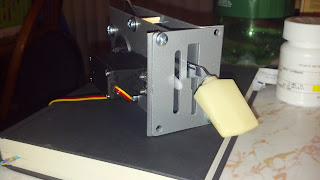
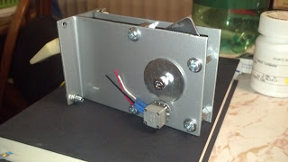
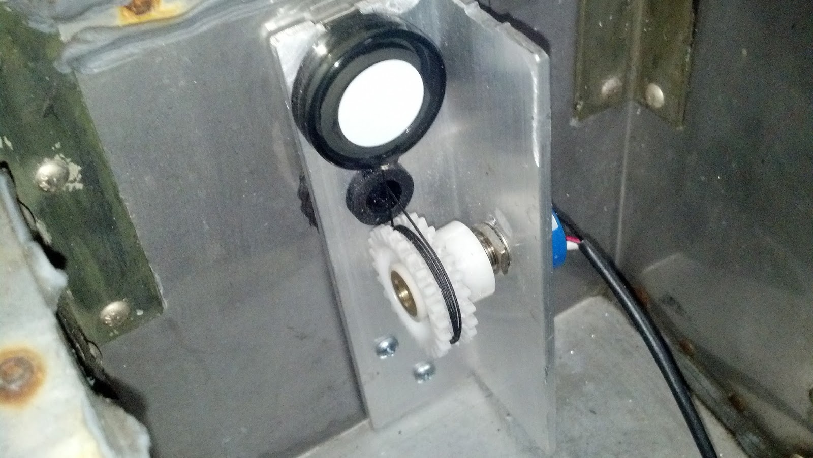
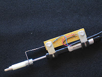
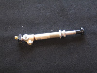
 As I said, I did get the elevator position sensor built and after all the complexity that I designed into the original idea it turned out to be embarrassingly simple. I can not take credit for the concept, unfortunately I can't find the link to the guy who posted the idea I ended up using. I originally wanted to use commercially made linear position sensors. That is, until I priced them... So then I was back to the drawing board designing a linkage for a rotary potentiometer to covert the 3.5 inches of linear motion into 340 degrees or rotary motion. This idea came from a fellow sim pit builder who used a rotary pot, an aluminum L bracket, and one of those retractable ID badge holders and fabricated a poor mans linear position indicator. I should have take a picture before I installed it but this pic will have to do. And, it works great!!! So, I am now considering a variation of this to replace the rudder pedal position indicator that I mentioned not liking in a prior blog post.
 The other bit of work I did before it got too cold was to rough in the surround sound speaker wiring and to fabricate the first of the two wing root air vents. Then I ran short of speaker wire before I was able to get the center speaker, sub, or but shaker runs done but have since purchased another spool and will get it done as soon as I have some time. sim moved into it's future space inside the heated portion of the house.
Hopefully last Winter will be the last winter where work stalls. By this fall I hope to have either heat in the garage and/or the
 I also finished the mechanical build on my flap control and flap position indicator. I had several ideas on how to do this but had not worked out a final design, I was going to use a slide pot until I ran across a very similar design concept to mine done my a fellow builder, Louie Mendez who owns DIY Realism and makes some great simulator parts. If you haven't already picked up on it from this and other blog posts sim pit builders tend to be a very collaborative community. Louie's
 design used a custom cut half moon gear and he was kind enough to send me an early prototype that I was able to adapt to my design. The end result was better than I had hoped for. It works great and doesn't look half bad considering I did all the heavy gauge sheet metal work without a sheer or a bending break... The only detail left is to put a return tension spring on the flap handle and do the graphics for the face plate. I've already tested the pot and servo motor operation with the sim and test fit the assembly in the fuselage.
 As the title of this blog post implies, most of the work since the last update has taken place at the test bench MIP. That being how I was going to build the avionics stack. The shortest route would be to purchase prefab'ed sim avionics, and there are some really good ones out there. But that would require far more cash outlay than is realistic for me. So, I have been looking at all sorts of options. The two biggest obstacles to building my own avionics stack were how to drive the 7 segment LED displays and how to fabricate realistic looking face plates. The answer to both and much more came while I was trying to find an alternative to the Phidgets boards I was originally planning to use. The Phidgets boards are great and I have them in mind for other projects, but I was running into a lot of hassles with the interface software not being as capable, or maybe more likely my not being capable of making it do what I wanted. What I came across was Arduino boards and an interface app developed by another sim enthusiast called Link2FS. The app is fantastic, and the guy who developed it, Jim, is now developing a more advanced multi board version. Like Louie, Jim is a real asset to the sim building community. I can't say enough about them and the work they are doing.
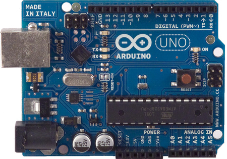
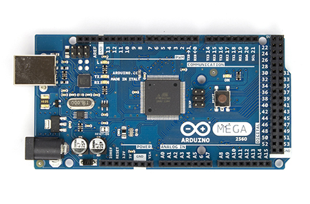 So far I have two Arduino boards, a Mega and an Uno and have added to them a relay shield, and a motor shield. By the time this portion of the build is done I will likely have one or maybe two more Arduino boards and another motor shield. I am also looking at solving for several other parts of the build using Arduinos. I am very impressed with what I have been able to accomplish despite my never having coded in C++ before. But to give credit where credit is due much of that progress has been helped along by Jim and the great community of builders over at www.mycockpit.org.
 I had already figured out how to handle all the rotary knobs and switches on the instrument panel and avionics stack so the next hurtle was the LEDs both single LED lamps and 7 Segment LEDs. As I mentioned above with the interface apps for the Phidgets LED controller not working out as planned, and the fact that Phidgets Inc. does not provide a 7 segment display solution I found myself working with Link2FS and Arduino boards. With those I have been able to get the following coded and tested so far.
It all looks like electric spaghetti on the bench at the moment but it all works and I am now sorting out the parts list to order what is needed for the final build.
I did run into a problem with daisy chaining the 7 segment displays. All the software and hardware documentation tells me I should be able to chain 8 of them together. But when I do the 4th and further displays act erratically. More testing and trouble shooting...
The other detail to work out is the worm gear design for the whiskey compass and the sync /calibration routine for "North" initialization. I bought an optical sensor for that but have not worked out the the details yet. Just another item on the rainy day list. To do a project like this you either need to love the details and technical challenges or have buckets of cash to pay other to overcome them. If not, you'll never get things done. Since I don't have buckets of cash, I am knee deep in the details and challenges.
Still left to prototype on the test bench in this phase:
 The other obstacle I mentioned above was the face plates for the various radios. The potential solution to this comes from fellow sim pit builder Louie Mendez who I mentioned above. He has the knowledge, skills, and tools to create very realistic looking face plates.
Having started his own business DIY Realism selling very realistic looking components at reasonable prices I am hoping his products will provide the cost effective solution I'm looking for. I will be ordering a Comm/Nav Radio Faceplate from him in the coming months and have inquired about the possibility of getting the other face plates as well. I have no doubt the faceplate will be of the same high quality as other parts I have purchased from him and he has been very helpful to myself and other pit builders in providing needed information.
So, that accounts for what happened in the Winter and the Spring. What about Summer... Well, you know that game "Rock, Paper, Scissors", my advise to everyone is never play that with a 2Lb Sledgehammer, a block of wood, and your hand. The hammer always wins!!! I managed to crush the middle finger on my left hand which basically put me out of commission as far as the pit build goes from mid May until just recently. The ER doc did a great job putting it back together and it's healing nicely. It works almost as good as it did before so I'm back at it now and pushing to get the sim room cleared out so I can get the fuselage moved in. I've also made a few good eBay acquisitions and worked out a few more design issues. But I'll post more about that in the next blog entry which I will try to do with much less delay than the last.
Hope all is well with you and the passing of the past few seasons has been kind to you.
Until the next update, enjoy the virtual skies and reach for the realism...
Much has happened since the last update. And, I typed the update below, more and more kept coming to mind that I had done since the last blog post.
Since the last update we have seen 3 seasons... The transition into winter started slow so I was able to get some more wiring done on the fuselage and I finally got the elevator position sensor done, but then the cold made it impractical to do much more in the garage. I managed a couple days hear and there but not much more. Heading back into Spring with plenty of winter weather early on but I was able to get a little more done as the temps slowly came up.
 As I said, I did get the elevator position sensor built and after all the complexity that I designed into the original idea it turned out to be embarrassingly simple. I can not take credit for the concept, unfortunately I can't find the link to the guy who posted the idea I ended up using. I originally wanted to use commercially made linear position sensors. That is, until I priced them... So then I was back to the drawing board designing a linkage for a rotary potentiometer to covert the 3.5 inches of linear motion into 340 degrees or rotary motion. This idea came from a fellow sim pit builder who used a rotary pot, an aluminum L bracket, and one of those retractable ID badge holders and fabricated a poor mans linear position indicator. I should have take a picture before I installed it but this pic will have to do. And, it works great!!! So, I am now considering a variation of this to replace the rudder pedal position indicator that I mentioned not liking in a prior blog post.
  The other bit of work I did before it got too cold was to rough in the surround sound speaker wiring and to fabricate the first of the two wing root air vents. Then I ran short of speaker wire before I was able to get the center speaker, sub, or but shaker runs done but have since purchased another spool and will get it done as soon as I have some time. sim moved into it's future space inside the heated portion of the house.
Hopefully last Winter will be the last winter where work stalls. By this fall I hope to have either heat in the garage and/or the
 I also finished the mechanical build on my flap control and flap position indicator. I had several ideas on how to do this but had not worked out a final design, I was going to use a slide pot until I ran across a very similar design concept to mine done my a fellow builder, Louie Mendez who owns DIY Realism and makes some great simulator parts. If you haven't already picked up on it from this and other blog posts sim pit builders tend to be a very collaborative community. Louie's
 As the title of this blog post implies, most of the work since the last update has taken place at the test bench MIP. That being how I was going to build the avionics stack. The shortest route would be to purchase prefab'ed sim avionics, and there are some really good ones out there. But that would require far more cash outlay than is realistic for me. So, I have been looking at all sorts of options. The two biggest obstacles to building my own avionics stack were how to drive the 7 segment LED displays and how to fabricate realistic looking face plates. The answer to both and much more came while I was trying to find an alternative to the Phidgets boards I was originally planning to use. The Phidgets boards are great and I have them in mind for other projects, but I was running into a lot of hassles with the interface software not being as capable, or maybe more likely my not being capable of making it do what I wanted. What I came across was Arduino boards and an interface app developed by another sim enthusiast called Link2FS. The app is fantastic, and the guy who developed it, Jim, is now developing a more advanced multi board version. Like Louie, Jim is a real asset to the sim building community. I can't say enough about them and the work they are doing.So far I have two Arduino boards, a Mega and an Uno and have added to them a relay shield, and a motor shield. By the time this portion of the build is done I will likely have one or maybe two more Arduino boards and another motor shield. I am also looking at solving for several other parts of the build using Arduinos. I am very impressed with what I have been able to accomplish despite my never having coded in C++ before. But to give credit where credit is due much of that progress has been helped along by Jim and the great community of builders over at www.mycockpit.org.I had already figured out how to handle all the rotary knobs and switches on the instrument panel and avionics stack so the next hurtle was the LEDs both single LED lamps and 7 Segment LEDs. As I mentioned above with the interface apps for the Phidgets LED controller not working out as planned, and the fact that Phidgets Inc. does not provide a 7 segment display solution I found myself working with Link2FS and Arduino boards. With those I have been able to get the following coded and tested so far.
- The Comm and Nav Radio displays
- The ADF, DME, and Transponder display
- An LCD Clock, timer, temp, and, Voltmeter display
- An annunciator panel with warnings for low bus voltage, oil pressure, vacuum, and fuel, landing gear retracted warning, and an audible alarm and mute feature.
- Gear status lights showing down and locked, in transit, and retracted.
- The LED indicators for the avionics stack audio selector panel and OMI indicators.
- A servo motor driven flap position indicator
- A servo motor driven outside air temp thermometer (partial build, more to be done)
- And the beginning of a stepper motor driven Wet Compass.
 |
| Servo Motors for Flap Position indicator and Outside Air Temp Gauge. |
 |
| 7 Segment LED displays for the Radios, ADF, DME, Transponder, Auto Pilot, etc. |
 |
| Test board for all indicator lights |
 |
| LCD Display for Clock, Voltmeter, etc. |
 |
| Linear stepper motor to drive Whiskey Compass. This will be geared 10:1 to get better resolution and accuracy. |
 |
| DC Motor controller. Two will be used, one for the Wet Compass stepper motor, and another for the DC drive motor for the Elevator trim wheel. |
I did run into a problem with daisy chaining the 7 segment displays. All the software and hardware documentation tells me I should be able to chain 8 of them together. But when I do the 4th and further displays act erratically. More testing and trouble shooting...
The other detail to work out is the worm gear design for the whiskey compass and the sync /calibration routine for "North" initialization. I bought an optical sensor for that but have not worked out the the details yet. Just another item on the rainy day list. To do a project like this you either need to love the details and technical challenges or have buckets of cash to pay other to overcome them. If not, you'll never get things done. Since I don't have buckets of cash, I am knee deep in the details and challenges.
Still left to prototype on the test bench in this phase:
- The Auto Pilot
- The GPS Display
- The DC motor for the auto pilot elevator trim control
Having started his own business DIY Realism selling very realistic looking components at reasonable prices I am hoping his products will provide the cost effective solution I'm looking for. I will be ordering a Comm/Nav Radio Faceplate from him in the coming months and have inquired about the possibility of getting the other face plates as well. I have no doubt the faceplate will be of the same high quality as other parts I have purchased from him and he has been very helpful to myself and other pit builders in providing needed information.
So, that accounts for what happened in the Winter and the Spring. What about Summer... Well, you know that game "Rock, Paper, Scissors", my advise to everyone is never play that with a 2Lb Sledgehammer, a block of wood, and your hand. The hammer always wins!!! I managed to crush the middle finger on my left hand which basically put me out of commission as far as the pit build goes from mid May until just recently. The ER doc did a great job putting it back together and it's healing nicely. It works almost as good as it did before so I'm back at it now and pushing to get the sim room cleared out so I can get the fuselage moved in. I've also made a few good eBay acquisitions and worked out a few more design issues. But I'll post more about that in the next blog entry which I will try to do with much less delay than the last.
Hope all is well with you and the passing of the past few seasons has been kind to you.
Until the next update, enjoy the virtual skies and reach for the realism...
Sunday, October 28, 2012
A window into the soul... of a plane


 After re cleaning the metal surface and cutting the simulated leather upholstery fabric (I know, simulated leather for a simulated plane LOL ) to size, I made the cut outs for the defrost vent and the avionics stack cooling vent. I then had to mask off all the surfaces around the dash so I would not cause any problems with over spray when applying the adhesive. With that done I applied an aerosol adhesive to both the metal surface and the back of the upholstery fabric. When it got tacky enough I positioned the material over the vents and then smoothed it out, and pressed it down. It set up in a very short time and I was able to do some final trimming on around the vents and edges. With that done I reinstalled the trim rings around the vents and removed all the masking I had previously done. After that started the prep for the windshield install. The end result came out rather well.
 Even after reading the installers notes, installing the windshield was a far more involved and time consuming process than I thought it would be. While the windshield was made to order to fit the make, model, and year of aircraft it was by design still not an exact fit. The manufacturer explained to me that the sides and bottom edges are intentionally cut slightly oversize to allow for minor variations caused by normal stresses on the airframe. Because of this it is necessary to do a pre install test fit. It's dome without the felt gasket or caulking. With it in place the edges are marked allowing enough additional clearance for the felt gasketing, something I didn't allow enough for on one edge... Then the windshield is removed again and trimmed to size. I used a Dermal with a cutoff wheel to make the cuts.
Have you ever seen those "Blend-Tech" YouTube commercials where the guy puts everything from bic lighters to billiard balls into their blender, and grinds them to dust. It's an amazing blender, but I digress. At the end of each one of the videos he says "Bic lighter smoke, Don't breath that!" or Billiard Ball Smoke, Don't Breath That!", etc.. Now after cutting that windshield my strongest advice to anyone who cuts plexi' is "Plexiglas smoke, DON'T BREATH THAT!" I wore a respirator mask which helped keep the dust (and there was a lot of it) out of my lungs. But, it didn't help the huge amount that collected on my clothing and in my hair.
 It worked very well and all these steps took about two hours. After that I adhered the felt gasketing to all the edges and attempted to do the final install. That's where it got real difficult. Despite every blocking and jig arrangement I attempted I could not get the windshield into the upper mounting flange on the fuselage. I had to give in and decide it was a two person job. Thanks to a family member who was able to come over and work with me we were able to come up with a solution. Not an easy one, but the only one that worked. I am again amazed at the difficulty and complexity of the work that Airframe & Power Plant Mechanics do. After that I reinstalled the outside mounting trim and started the tedious but satisfying process of reinstalling the nearly 100 rivets.
And so ended my weekend, or at least the sim pit building portion. The rest of the family got home late Sunday afternoon and we spent time catching up on each others adventures. Mine you know about, there's was a great Girl Scout camping trip.
That's all for now. I'm off to do some more e-bay hunting to find the interior trim parts that mount against the newly installed window and to design the wing root end caps that will follow the forward contour of the windshield and cover where the wings used to mount. More to come when I make more progress....
Tuesday, October 16, 2012
Yokes and Control Wiring
 I made a little more progress over the weekend. The pair of yokes I purchased both had Mic key buttons built in, however the pilots button was not working. I managed to find an exact match to the very tiny micro switch at a local supplier and purchased one. I wired the new switch into the pilot's yoke, which was a bit of a pain. And, decided before installing the yokes to test them one last time. Somehow, after sitting on a shelf for a year the copilots button decided it no longer wanted to work, and worse, there's no service slack in the wire leads. So I decided to install the yoke anyway and will make that repair at a later time., but without that slack it requires that I cut into the back side of the molded rubber grip to extend the leads. And I thought the pilots side was a pain...

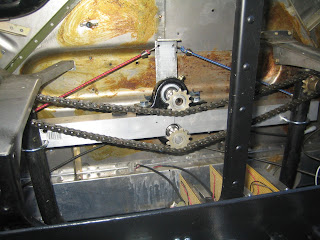
I also found a design flaw with my aileron linkage. While the chain has sufficient tension to move the sprockets without any drag the minimal contact with the chain due to the angle causes the top sprocket to jump teeth anytime the tension gets to high. To overcome this for now I've added some temporary chain tensioners in the form of a pair of mini bungee cords. You can see the pilot side bungee (red) in the this pic. This will all be replaced later by a more mechanically sound spring loaded idler sprocket.
I'll post more as it happens, but that's all for now.
Monday, October 1, 2012
Back at it after a brief hiatus...
Just a quick post to let everyone know that I am back in the virtual left seat after a summer hiatus. I had not intended on being away from the build for so long, but real life must take priority over virtual life, at least my wife keeps telling me that ;-) so other things required my attention for a few months. At this point I'm just spooling up again, reviewing my project plan, and mapping out the next few months of build time.
I just purchased the replacement windshield and should have it in hand in about two weeks. After that is installed it clears several obstacles for other build elements such as wing root end caps and forward air vents. With those done and the primary sub woofer mounted I can then build the rear external cover.
Other items that are on the short list are mounting the rudder pedal position sensor, finishing the design of the elevator linkage and installing it, installing the yoke shafts, yokes, and yoke mounted mic key switches. Then doing a full test of all the installed I/O. Unfortunately that includes repairing the magneto key switch which has failed after only light use. I also need to do the last of the cosmetic work on the lower instrument panel and get the last couple switches installed and wired.
I really need to get a safe heat source installed in my work area so that I can continue work this winter. I am thinking that repair and restoration of some of the interior trim panels is on the agenda for the winter months. After I figure out how far I can get with that I will then have a better idea of what interior trim I need to source elsewhere.
And, of course, I change my mind about the best way to handle the initial Instrument Panel build at least 4 times a week. So, I am waiting on that as long as possible to allow for more research and make sure I don't start investing in one of the more expensive parts of the build only to change my mind several dollars later.
That's all for now. Hopefully it won't be a long time before my next update.
 Tom
TomPS: remember those pesky little connectors I could not find earlier this year. Well, now that I have decided not to use that circuit card for the sim, of course, I found a source for them. So, I decided to order enough for that one board and I'll be adding a few switches to my Desktop Sim Pit just to allow for more complex aircraft simulation. Why let a good encoder card go t waist.
Wednesday, March 14, 2012
Crazy Busy, but too cold to build . . .
We're finally seeing some warmer weather and with that I hope to regain some momentum on the pit build. I have been insanely busy at work so hours had to be trimmed from the build schedule. That won't end any time soon, but with the weather warming up the garage temp is coming up as well and that will open up some later evening hours to get more hands on work done on the fuselage. I really can't wait to get to a point where the Sim room is built and I can move everything in there. That's likely not coming until later this year though, but hopefully ahead of next winters cold weather.
Not much to show from the past month in the way of pic's. I'll try to come back and add the few that I have when time permits. I got a bit more done on the lower instrument panel wire harness, and hit a real technical snag on the software. As you may know from the software page on my web site I am using Phidgets boards for some of the I/O. In particular LED indicators and servo motors. I had about 60% or 70% of my scripting done in a great app called Fs2Phidget Version 5 that was written by another Sim pit builder. Unfortunately (for some very good reasons that I can't fault him for) the developer has made a decision to moth ball version 5 and focus his efforts on further development of the prior version. The big innovation in version 5, besides a total re-write of the core app, was a fantastic graphical user interface. This allowed me to draw schematic equivalents of the I/O logic and insert programming elements and variables as if they were components. As an Electrical Engineer this really worked for me. Unfortunately version 4 which he will be moving forward with again is table based and non-graphical. It's scripting files are not at all compatible with the scripting I've developed in version 5.
My version 5 work came crashing to an end when I added the servo controller board. It required a driver library update and when I loaded that FS2Phidgets V5 ceased to speak to the hardware. So I'm back to the drawing board and using version 4. It's showing no problems speaking to the Phidgets boards and to FSX. It's scripting concept is very different but I'm adapting and learning as I go.
More to come soon...
Sunday, February 5, 2012
Installed some of the controls
I finally feel like I've started making progress again. I finished the engine controls, the aileron linkage and position sensor, and the brake master cylinders. I got started on the elevator position sensor but need to solve for the centering springs before I can do much more on that. The elevator linkage is easy enough since the stock Cessna linkage lends itself perfectly to the task, so it's just a matter of integrating centering springs into it.
For the elevator and aileron controls, and perhaps later the rudder pedals, I'm hoping the centering springs are only a short term need, as I have started to save pennies for force feedback. I've already made accommodations for the force feedback linkage in what I just installed for the elevator and aileron controls, but I haven't quite figured on how to integrate it into the rudder pedals yet. Ideas are stirring but nothing solid yet...
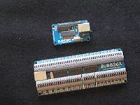 I've been bogged down for a while now trying to find viable connectors for my older Leo Bodnar BU0836A card. Bodnar's site has shown the connector as out of stock for several months now. I can only assume that, even though it's still available, with the board being superseded by the BU0836X that Leo has no intent of supplying the connectors any longer. I tested a half dozen different connectors including some that other seemed to have been able to use on their cards. I finally gave in and bought a replacement BU0836X. The "A" card won't go to waist as I will continue to use it for prototyping and may add it to the desktop pit. The new card is larger, but has wire connectors mounted on the board so that'll make the install so much easier.
 So, you saw the initial build on the engine controls in an earlier post. The only remaining step was to wire the pigtails. I decided to put 3 pin connectors on the pigtails to make things a little easier for future maintenance. With that done I installed them this past weekend.
I did run into a minor clearance problem between then and the Aileron linkage but was able to solve that easily. The spacing is a bit tight between the controls and to the right the landing gear switch, to the left the sson to be built flap switch. The flap switch may prove to be a bit more challenging given the tight space but should still be workable.
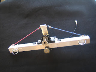 The aileron crossbar mounted easily and other than having to take an additional link out of the chain to raise it up another 1/2" and resolve the above mentioned clearance problem it dropped in as planned. The setup consists of a cross bar that mounts with u-bolts to the Cessna yoke Y-bar uprights. Centered on the cross bar are two bearing pillow blocks with Cessna yoke sprockets on 1/2" shafts. The upper has the return springs and rotation limiter bar on it. It will also be the used to connect the FFB system in the future via a universal joint on the opposite side of the bearing block. The lower shaft has a gear arrangement on
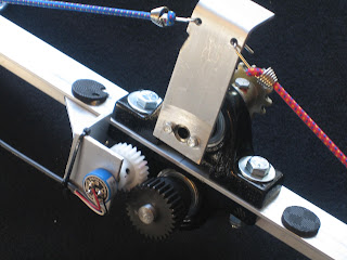 the back that connects it to the position sensing potentiometer. The gearing is setup to convert the 180 degrees of yoke rotation to 340 degrees of potentiometer rotation. Unlike that rudder or elevator linkages, that have hard stops on them, there's a potential with this aileron linkage arrangement for over torquing on the yoke to exceed the limit set by the stop arm. Because of this I chose a continuous rotation pot to eliminate the possibility of damaging a normal 340 or 360 degree pot with stops. To allow for full down elevator deflection the design required that I cut a 4" x 6" opening in the firewall.
 That will also be the entry point for the force feedback drive shaft at a future date. I'm not thrilled with the bungy chord arrangement for return springs but it does seem to be working. If I can come up with something better before I install the instrument panel I may be doing an upgrade. Gotta keep telling myself though that they'll be coming out as soon as I can afford the FFB system. Everything else in this portion of the install went in as designed and I'm quite satisfied with the results.
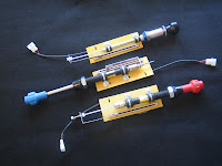
 The brake master cylinders came out far better than I thought they would. I purchased some 8" mini gas springs, I did have to cut them down another 1/2" but other than that no modifications. I added a mounting board to the piston housing with a 25mm slide pot. and a linkage to the piston shaft that was held in place by a pair of shaft collars. I also installed a couple 1" spacers above that to prevent the brakes from being pushed too far and damaging the slide pots. While the design is simple, and the build was easy, installing them reminded me again why I will never be a General Aviation mechanic. I am convinced that to qualify as an A&P mechanic you need a second wrist and elbow in each arm and hands as small as a chipmunks paws. They did eventually go in, but that was after scraping a little flesh off my hands and the application of some colorful language.
 I also decided to replace the electrical switch I had put in as a dual function fuel pump and primer switch with an actual fuel primer. All I had to do was drill out the back end and fit a momentary push button switch in it. While that solves for a more realistic primer, it does leave me looking for another fuel pump switch for emulating newer aircraft. Space on the lower instrument panel is getting tight, but there is some space left. While as planned it is a generic sim pit I am still trying to stay as close as possible to the Cessna 172 format.
So that's where the work wrapped up this weekend. This coming week I'll be pulling out the wiring nail board again to retrofit it with the new bodnar card to the wire harness with the hope of getting it installed next weekend or the weekend after.
For the elevator and aileron controls, and perhaps later the rudder pedals, I'm hoping the centering springs are only a short term need, as I have started to save pennies for force feedback. I've already made accommodations for the force feedback linkage in what I just installed for the elevator and aileron controls, but I haven't quite figured on how to integrate it into the rudder pedals yet. Ideas are stirring but nothing solid yet...


 So, you saw the initial build on the engine controls in an earlier post. The only remaining step was to wire the pigtails. I decided to put 3 pin connectors on the pigtails to make things a little easier for future maintenance. With that done I installed them this past weekend.
I did run into a minor clearance problem between then and the Aileron linkage but was able to solve that easily. The spacing is a bit tight between the controls and to the right the landing gear switch, to the left the sson to be built flap switch. The flap switch may prove to be a bit more challenging given the tight space but should still be workable.
 The aileron crossbar mounted easily and other than having to take an additional link out of the chain to raise it up another 1/2" and resolve the above mentioned clearance problem it dropped in as planned. The setup consists of a cross bar that mounts with u-bolts to the Cessna yoke Y-bar uprights. Centered on the cross bar are two bearing pillow blocks with Cessna yoke sprockets on 1/2" shafts. The upper has the return springs and rotation limiter bar on it. It will also be the used to connect the FFB system in the future via a universal joint on the opposite side of the bearing block. The lower shaft has a gear arrangement on


 The brake master cylinders came out far better than I thought they would. I purchased some 8" mini gas springs, I did have to cut them down another 1/2" but other than that no modifications. I added a mounting board to the piston housing with a 25mm slide pot. and a linkage to the piston shaft that was held in place by a pair of shaft collars. I also installed a couple 1" spacers above that to prevent the brakes from being pushed too far and damaging the slide pots. While the design is simple, and the build was easy, installing them reminded me again why I will never be a General Aviation mechanic. I am convinced that to qualify as an A&P mechanic you need a second wrist and elbow in each arm and hands as small as a chipmunks paws. They did eventually go in, but that was after scraping a little flesh off my hands and the application of some colorful language.
 I also decided to replace the electrical switch I had put in as a dual function fuel pump and primer switch with an actual fuel primer. All I had to do was drill out the back end and fit a momentary push button switch in it. While that solves for a more realistic primer, it does leave me looking for another fuel pump switch for emulating newer aircraft. Space on the lower instrument panel is getting tight, but there is some space left. While as planned it is a generic sim pit I am still trying to stay as close as possible to the Cessna 172 format.
So that's where the work wrapped up this weekend. This coming week I'll be pulling out the wiring nail board again to retrofit it with the new bodnar card to the wire harness with the hope of getting it installed next weekend or the weekend after.
Subscribe to:
Posts (Atom)