My Cessna Sim Project

My Cessna Sim Project
To visit my project web site click on the image above or go to: www.mycessnasim.info

Sunday, October 28, 2012

A window into the soul... of a plane

Well, not really!  But, it is a windshield into the cockpit of my sim!  Installing the new windshield was the single biggest work effort in the fuselage restoration since the time I cut the fuselage down to size.  I had a great weekend to get it done since the my wife and daughters were away.  Other than a few hours for sleeping, eating, and church I started Friday night and worked through Sunday late afternoon.  Of course the prerequisite to installing the windshield was to install the new dashboard upholstery.  Everything worked out well and if i ever do such a project again I can say for sure that I've learned some valuable lessons that will make it far easier.   Of the almost 100 rivets that hold the windshield in place I have a couple left to reinstall but ran out.  I had enough, I thought, but didn't realize that a few of them had to pass through a thicker piece of material so I need to buy some longer rivets this week.

After re cleaning the metal surface and cutting the simulated leather upholstery fabric (I know, simulated leather for a simulated plane LOL ) to size, I made the cut outs for the defrost vent and the avionics stack cooling vent.  I then had to mask off all the surfaces around the dash so I would not cause any problems with over spray when applying the adhesive.  With that done I applied an aerosol adhesive to both the metal surface and the back of the upholstery fabric.  When it got tacky enough I positioned the material over the vents and then smoothed it out, and pressed it down.  It set up in a very short time and I was able to do some final trimming on around the vents and edges.  With that done I reinstalled the trim rings around the vents and removed all the masking I had previously done.  After that started the prep for the windshield install. The end result came out rather well.

Even after reading the installers notes, installing the windshield was a far more involved and time consuming process than I thought it would be.  While the windshield was made to order to fit the make, model, and year of aircraft it was by design still not an exact fit.  The manufacturer explained to me that the sides and bottom edges are intentionally cut slightly oversize to allow for minor variations caused by normal stresses on the airframe.  Because of this it is necessary to do a pre install test fit.  It's dome without the felt gasket or caulking.  With it in place the edges are marked allowing enough additional clearance for the felt gasketing, something I didn't allow enough for on one edge...  Then the windshield is removed again and trimmed to size.  I used a Dermal with a cutoff wheel to make the cuts.

Have you ever seen those "Blend-Tech" YouTube commercials where the guy puts everything from bic lighters to billiard balls into their blender, and grinds them to dust.  It's an amazing blender, but I digress.  At the end of each one of the videos he says "Bic lighter smoke, Don't breath that!" or Billiard Ball Smoke, Don't Breath That!", etc..  Now after cutting that windshield my strongest advice to anyone who cuts plexi' is "Plexiglas smoke, DON'T BREATH THAT!" I wore a respirator mask which helped keep the dust (and there was a lot of it) out of my lungs.  But, it didn't help the huge amount that collected on my clothing and in my hair.

It worked very well and all these steps took about two hours.  After that I adhered the felt gasketing to all the edges and attempted to do the final install.  That's where it got real difficult.  Despite every blocking and jig arrangement I attempted I could not get the windshield into the upper mounting flange on the fuselage.  I had to give in and decide it was a two person job.  Thanks to a family member who was able to come over and work with me we were able to come up with a solution.  Not an easy one, but the only one that worked.  I am again amazed at the difficulty and complexity of the work that Airframe & Power Plant Mechanics do.  After that I reinstalled the outside mounting trim and started the tedious but satisfying process of reinstalling the nearly 100 rivets.

And so ended my weekend, or at least the sim pit building portion.  The rest of the family got home late Sunday afternoon and we spent time catching up on each others adventures.  Mine you know about, there's was a great Girl Scout camping trip.

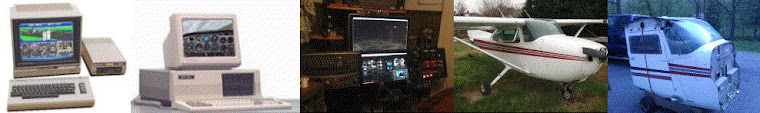
That's all for now.  I'm off to do some more e-bay hunting to find the interior trim parts that mount against the newly installed window and to design the wing root end caps that will follow the forward contour of the windshield and cover where the wings used to mount.  More to come when I make more progress....

Tuesday, October 16, 2012

Yokes and Control Wiring

I made a little more progress over the weekend.  The pair of yokes I purchased both had Mic key buttons built in, however the pilots button was not working.  I managed to find an exact match to the very tiny micro switch at a local supplier and purchased one.  I wired the new switch into the pilot's yoke, which was a bit of a pain.  And, decided before installing the yokes to test them one last time.  Somehow, after sitting on a shelf for a year the copilots button decided it no longer wanted to work, and worse, there's no service slack in the wire leads.  So I decided to install the yoke anyway and will make that repair at a later time., but without that slack it requires that I cut into the back side of the molded rubber grip to extend the leads.  And I thought the pilots side was a pain...


Well beyond that I got the engine control, aileron, and rudder axis position sensors connected to the controller and tested through to FSX on my laptop (my test machine).  While it did work, I'm not happy with the rudder position sensor so I am looking at other options for it.  However, all else went in and tested good.  Next up, the elevator control position sensor. I had a design and after buying a few basic parts and test fitting everything I am not so sure about it so that to is back on the drawing board for the moment.


I also found a design flaw with my aileron linkage. While the chain has sufficient tension to move the sprockets without any drag the minimal contact with the chain due to the angle causes the top sprocket to jump teeth anytime the tension gets to high.  To overcome this for now I've added some temporary chain tensioners in the form of a pair of mini bungee cords.  You can see the pilot side bungee (red) in the this pic.  This will all be replaced later by a more mechanically sound spring loaded idler sprocket.

I'll post more as it happens, but that's all for now.

Monday, October 1, 2012

Back at it after a brief hiatus...


Just a quick post to let everyone know that I am back in the virtual left seat after a summer hiatus.  I had not intended on being away from the build for so long, but real life must take priority over virtual life, at least my wife keeps telling me that ;-) so other things required my attention for a few months.  At this point I'm just spooling up again, reviewing my project plan, and mapping out the next few months of build time.

I just purchased the replacement windshield and should have it in hand in about two weeks.  After that is installed it clears several obstacles for other build elements such as wing root end caps and forward air vents. With those done and the primary sub woofer mounted I can then build the rear external cover.

Other items that are on the short list are mounting the rudder pedal position sensor, finishing the design of the elevator linkage and installing it, installing the yoke shafts, yokes, and yoke mounted mic key switches.  Then doing a full test of all the installed I/O.  Unfortunately that includes repairing the magneto key switch which has failed after only light use.  I also need to do the last of the cosmetic work on the lower instrument panel and get the last couple switches installed and wired.

I really need to get a safe heat source installed in my work area so that I can continue work this winter.  I am thinking that repair and restoration of some of the interior trim panels is on the agenda for the winter months. After I figure out how far I can get with that I will then have a better idea of what interior trim I need to source elsewhere.

And, of course, I change my mind about the best way to handle the initial Instrument Panel build at least 4 times a week.  So, I am waiting on that as long as possible to allow for more research and make sure I don't start investing in one of the more expensive parts of the build only to change my mind several dollars later.

That's all for now.  Hopefully it won't be a long time before my next update.
Tom

PS: remember those pesky little connectors I could not find earlier this year.  Well, now that I have decided not to use that circuit card for the sim, of course, I found a source for them.  So, I decided to order enough for that one board and I'll be adding a few switches to my Desktop Sim Pit just to allow for more complex aircraft simulation.  Why let a good encoder card go t waist.

Wednesday, March 14, 2012

Crazy Busy, but too cold to build . . .

We're finally seeing some warmer weather and with that I hope to regain some momentum on the pit build.  I have been insanely busy at work so hours had to be trimmed from the build schedule.  That won't end any time soon, but with the weather warming up the garage temp is coming up as well and that will open up some later evening hours to get more hands on work done on the fuselage.  I really can't wait to get to a point where the Sim room is built and I can move everything in there.  That's likely not coming until later this year though, but hopefully ahead of next winters cold weather.

Not much to show from the past month in the way of pic's.  I'll try to come back and add the few that I have when time permits.  I got a bit more done on the lower instrument panel wire harness, and hit a real technical snag on the software.  As you may know from the software page on my web site I am using Phidgets boards for some of the I/O.  In particular LED indicators and servo motors.  I had about 60% or 70% of my scripting done in a great app called Fs2Phidget Version 5 that was written by another Sim pit builder.  Unfortunately (for some very good reasons that I can't fault him for) the developer has made a decision to moth ball version 5 and focus his efforts on further development of the prior version.  The big innovation in version 5, besides a total re-write of the core app, was a fantastic graphical user interface.  This allowed me to draw schematic equivalents of the I/O logic and insert programming elements and variables as if they were components.  As an Electrical Engineer this really worked for me.  Unfortunately version 4  which he will be moving forward with again is table based and non-graphical.  It's scripting files are not at all compatible with the scripting I've developed in version 5.

My version 5 work came crashing to an end when I added the servo controller board.  It required a driver library update and when I loaded that FS2Phidgets V5 ceased to speak to the hardware.  So I'm back to the drawing board and using version 4.  It's showing no problems speaking to the Phidgets boards and to FSX.  It's scripting concept is very different but I'm adapting and learning as I go.

More to come soon...

Sunday, February 5, 2012

Installed some of the controls

I finally feel like I've started making progress again.  I finished the engine controls, the aileron linkage and position sensor, and the brake master cylinders.  I got started on the elevator position sensor but need to solve for the centering springs before I can do much more on that.  The elevator linkage is easy enough since the stock Cessna linkage lends itself perfectly to the task, so it's just a matter of integrating centering springs into it.

For the elevator and aileron controls, and perhaps later the rudder pedals, I'm hoping the centering springs are only a short term need, as I have started to save pennies for force feedback.  I've already made accommodations for the force feedback linkage in what I just installed for the elevator and aileron controls, but I haven't quite figured on how to integrate it into the rudder pedals yet.  Ideas are stirring but nothing solid yet...

I've been bogged down for a while now trying to find viable connectors for my older Leo Bodnar BU0836A card.  Bodnar's site has shown the connector as out of stock for several months now.  I can only assume that, even though it's still available, with the board being superseded by the BU0836X that Leo has no intent of supplying the connectors any longer.  I tested a half dozen different connectors including some that other seemed to have been able to use on their cards.  I finally gave in and bought a replacement BU0836X.  The "A" card won't go to waist as I will continue to use it for prototyping and may add it to the desktop pit.  The new card is larger, but has wire connectors mounted on the board so that'll make the install so much easier.

So, you saw the initial build on the engine controls in an earlier post.  The only remaining step was to wire the pigtails.  I decided to put 3 pin connectors on the pigtails to make things a little easier for future maintenance.  With that done I installed them this past weekend.
 I did run into a minor clearance problem between then and the Aileron linkage but was able to solve that easily.  The spacing is a bit tight between the controls and to the right the landing gear switch, to the left the sson to be built flap switch.  The flap switch may prove to be a bit more challenging given the tight space but should still be workable.

The aileron crossbar mounted easily and other than having to take an additional link out of the chain to raise it up another 1/2" and resolve the above mentioned clearance problem it dropped in as planned.   The setup consists of a cross bar that mounts with u-bolts to the Cessna yoke Y-bar uprights.  Centered on the cross bar are two bearing pillow blocks with Cessna yoke sprockets on 1/2" shafts.  The upper has the return springs and rotation limiter bar on it.  It will also be the used to connect the FFB system in the future via a universal joint on the opposite side of the bearing block.  The lower shaft has a gear arrangement on

the back that connects it to the position sensing potentiometer.  The gearing is setup to convert the 180 degrees of yoke rotation to 340 degrees of potentiometer rotation.  Unlike that rudder or elevator linkages, that have hard stops on them, there's a potential with this aileron linkage arrangement for over torquing on the yoke to exceed the limit set by the stop arm.  Because of this I chose a continuous rotation pot to eliminate the possibility of damaging a normal 340 or 360 degree pot with stops.  To allow for full down elevator deflection the design required that I cut a 4" x 6" opening in the firewall. 
That will also be the entry point for the force feedback drive shaft at a future date.  I'm not thrilled with the bungy chord arrangement for return springs but it does seem to be working.  If I can come up with something better before I install the instrument panel I may be doing an upgrade.  Gotta keep telling myself though that they'll be coming out as soon as I can afford the FFB system.  Everything else in this portion of the install went in as designed and I'm quite satisfied with the results.

The brake master cylinders came out far better than I thought they would.  I purchased some 8" mini gas springs, I did have to cut them down another 1/2" but other than that no modifications.  I added a mounting board  to the piston housing with a 25mm slide pot.  and a linkage to the piston shaft that was held in place by a pair of shaft collars.  I also installed a couple 1" spacers above that to prevent the brakes from being pushed too far and damaging the slide pots.  While the design is simple, and the build was easy, installing them reminded me again why I will never be a General Aviation mechanic.  I am convinced that to qualify as an A&P mechanic you need a second wrist and elbow in each arm and hands as small as a chipmunks paws.  They did eventually go in, but that was after scraping a little flesh off my hands and the application of some colorful language.

I also decided to replace the electrical switch I had put in as a dual function fuel pump and primer switch with an actual fuel primer.  All I had to do was drill out the back end and fit a momentary push button switch in it.  While that solves for a more realistic primer, it does leave me looking for another fuel pump switch for emulating newer aircraft.  Space on the lower instrument panel is getting tight, but there is some space left.  While as planned it is a generic sim pit I am still trying to stay as close as possible to the Cessna 172 format.

So that's where the work wrapped up this weekend.  This coming week I'll be pulling out the wiring nail board again to retrofit it with the new bodnar card to the wire harness with the hope of getting it installed next weekend or the weekend after.

Monday, January 9, 2012

Santa was good to me but not a lot happened on the Sim...

Sorry for the long silence.  The holidays have been great, time with family and friends, some online flying, and my youngest daughter has started to take an online ground school through the Young Eagles program.  Santa was very good to me and my sim, a new bench grinder that will make some of the build work so much easier.  Several new scenery enhancement applications that I've started testing on the desktop pit.  And, two new aircraft: A Beach Bonanza V35B, yes the good old V-Tail, and a Cessna 340 twin.  The Bonanza has fast become my favorite Low wing by a long shot.

Anyway, not much build activity during that time.  But I just got started again this past weekend and have the new Aileron linkage about 80% done.  I'm hoping to post pictures in a week or so, but, have several other things going that will make progress slow this month.

Just a quick post to let you know that I'm still active.