
Much has happened since the last update. And, I typed the update below, more and more kept coming to mind that I had done since the last blog post.
Since the last update we have seen 3 seasons... The transition into winter started slow so I was able to get some more wiring done on the fuselage and I finally got the elevator position sensor done, but then the cold made it impractical to do much more in the garage. I managed a couple days hear and there but not much more. Heading back into Spring with plenty of winter weather early on but I was able to get a little more done as the temps slowly came up.
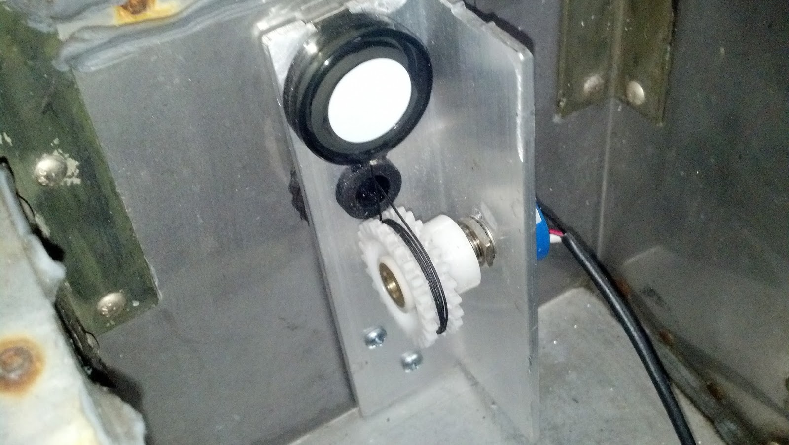 As I said, I did get the elevator position sensor built and after all the complexity that I designed into the original idea it turned out to be embarrassingly simple. I can not take credit for the concept, unfortunately I can't find the link to the guy who posted the idea I ended up using. I originally wanted to use commercially made linear position sensors. That is, until I priced them... So then I was back to the drawing board designing a linkage for a rotary potentiometer to covert the 3.5 inches of linear motion into 340 degrees or rotary motion. This idea came from a fellow sim pit builder who used a rotary pot, an aluminum L bracket, and one of those retractable ID badge holders and fabricated a poor mans linear position indicator. I should have take a picture before I installed it but this pic will have to do. And, it works great!!! So, I am now considering a variation of this to replace the rudder pedal position indicator that I mentioned not liking in a prior blog post.
  The other bit of work I did before it got too cold was to rough in the surround sound speaker wiring and to fabricate the first of the two wing root air vents. Then I ran short of speaker wire before I was able to get the center speaker, sub, or but shaker runs done but have since purchased another spool and will get it done as soon as I have some time. sim moved into it's future space inside the heated portion of the house.
Hopefully last Winter will be the last winter where work stalls. By this fall I hope to have either heat in the garage and/or the
 I also finished the mechanical build on my flap control and flap position indicator. I had several ideas on how to do this but had not worked out a final design, I was going to use a slide pot until I ran across a very similar design concept to mine done my a fellow builder, Louie Mendez who owns DIY Realism and makes some great simulator parts. If you haven't already picked up on it from this and other blog posts sim pit builders tend to be a very collaborative community. Louie's
 As the title of this blog post implies, most of the work since the last update has taken place at the test bench MIP. That being how I was going to build the avionics stack. The shortest route would be to purchase prefab'ed sim avionics, and there are some really good ones out there. But that would require far more cash outlay than is realistic for me. So, I have been looking at all sorts of options. The two biggest obstacles to building my own avionics stack were how to drive the 7 segment LED displays and how to fabricate realistic looking face plates. The answer to both and much more came while I was trying to find an alternative to the Phidgets boards I was originally planning to use. The Phidgets boards are great and I have them in mind for other projects, but I was running into a lot of hassles with the interface software not being as capable, or maybe more likely my not being capable of making it do what I wanted. What I came across was Arduino boards and an interface app developed by another sim enthusiast called Link2FS. The app is fantastic, and the guy who developed it, Jim, is now developing a more advanced multi board version. Like Louie, Jim is a real asset to the sim building community. I can't say enough about them and the work they are doing.
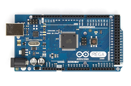 So far I have two Arduino boards, a Mega and an Uno and have added to them a relay shield, and a motor shield. By the time this portion of the build is done I will likely have one or maybe two more Arduino boards and another motor shield. I am also looking at solving for several other parts of the build using Arduinos. I am very impressed with what I have been able to accomplish despite my never having coded in C++ before. But to give credit where credit is due much of that progress has been helped along by Jim and the great community of builders over at www.mycockpit.org.
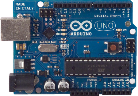 I had already figured out how to handle all the rotary knobs and switches on the instrument panel and avionics stack so the next hurtle was the LEDs both single LED lamps and 7 Segment LEDs. As I mentioned above with the interface apps for the Phidgets LED controller not working out as planned, and the fact that Phidgets Inc. does not provide a 7 segment display solution I found myself working with Link2FS and Arduino boards. With those I have been able to get the following coded and tested so far.
- The Comm and Nav Radio displays
- The ADF, DME, and Transponder display
- An LCD Clock, timer, temp, and, Voltmeter display
- An annunciator panel with warnings for low bus voltage, oil pressure, vacuum, and fuel, landing gear retracted warning, and an audible alarm and mute feature.
- Gear status lights showing down and locked, in transit, and retracted.
- The LED indicators for the avionics stack audio selector panel and OMI indicators.
- A servo motor driven flap position indicator
- A servo motor driven outside air temp thermometer (partial build, more to be done)
- And the beginning of a stepper motor driven Wet Compass.
 |
| Servo Motors for Flap Position indicator and Outside Air Temp Gauge. |
 |
| 7 Segment LED displays for the Radios, ADF, DME, Transponder, Auto Pilot, etc. |
 |
| Test board for all indicator lights |
 |
| LCD Display for Clock, Voltmeter, etc. |
 |
| Linear stepper motor to drive Whiskey Compass. This will be geared 10:1 to get better resolution and accuracy. |
 |
| DC Motor controller. Two will be used, one for the Wet Compass stepper motor, and another for the DC drive motor for the Elevator trim wheel. |
I did run into a problem with daisy chaining the 7 segment displays. All the software and hardware documentation tells me I should be able to chain 8 of them together. But when I do the 4th and further displays act erratically. More testing and trouble shooting...
The other detail to work out is the worm gear design for the whiskey compass and the sync /calibration routine for "North" initialization. I bought an optical sensor for that but have not worked out the the details yet. Just another item on the rainy day list. To do a project like this you either need to love the details and technical challenges or have buckets of cash to pay other to overcome them. If not, you'll never get things done. Since I don't have buckets of cash, I am knee deep in the details and challenges.
Still left to prototype on the test bench in this phase:
- The Auto Pilot
- The GPS Display
- The DC motor for the auto pilot elevator trim control
Having started his own business DIY Realism selling very realistic looking components at reasonable prices I am hoping his products will provide the cost effective solution I'm looking for. I will be ordering a Comm/Nav Radio Faceplate from him in the coming months and have inquired about the possibility of getting the other face plates as well. I have no doubt the faceplate will be of the same high quality as other parts I have purchased from him and he has been very helpful to myself and other pit builders in providing needed information.
So, that accounts for what happened in the Winter and the Spring. What about Summer... Well, you know that game "Rock, Paper, Scissors", my advise to everyone is never play that with a 2Lb Sledgehammer, a block of wood, and your hand. The hammer always wins!!! I managed to crush the middle finger on my left hand which basically put me out of commission as far as the pit build goes from mid May until just recently. The ER doc did a great job putting it back together and it's healing nicely. It works almost as good as it did before so I'm back at it now and pushing to get the sim room cleared out so I can get the fuselage moved in. I've also made a few good eBay acquisitions and worked out a few more design issues. But I'll post more about that in the next blog entry which I will try to do with much less delay than the last.
Hope all is well with you and the passing of the past few seasons has been kind to you.
Until the next update, enjoy the virtual skies and reach for the realism...